|
As mentioned previously uSCADA(p) allows the user to create a basic interface that is driven from
the data that is retrieved in the MODBUS read cycle, or to take user entries and make MODBUS writes to the slave device. The creation of a simple interface is briefly outlined below that uses one of each of the four element types available, these are namely DI (Digital Inputs), AI (Analogue Inputs), DO (Digital Outputs) and AO (Analogue Outputs).
To facilitate this program we will set up the MODBUS Comms as below:
Number of reads: 2
Start of Reads: 40001
Number of Writes: 2
Start of Writes: 40010
this will give us an I/O map equate to:
In: 0 = 40001
In: 1 = 40002
Out:0 = 40010
Out:1 = 40011
this information will be used when we construct the interface in a moment.
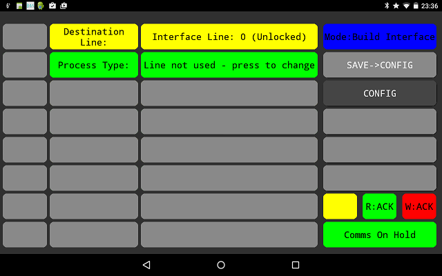
To change to the interface builder select the change mode button and
pick build interface from the list. on doing so you should then see:
DI - Digital Input Element:
If we press the line marked up "line not used - press to change" a pick list will appear that will allow us to choose the function of interface line: 0.
For now if we select Digital input, the display will then change to that shown below. For each input type a number of screens will need to be populated, for the digital input element there are 3 screens "i/o type", "True States" and "False states". These can accessed by simply touching the tags names for the sections.
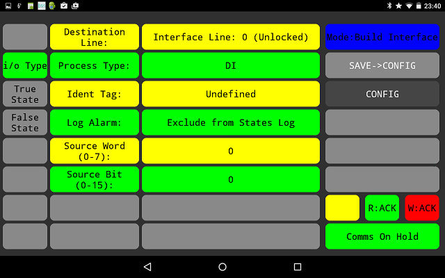
Here we need to supply specific information in order to build the digital input display line.
The function of these are briefly outlined below:
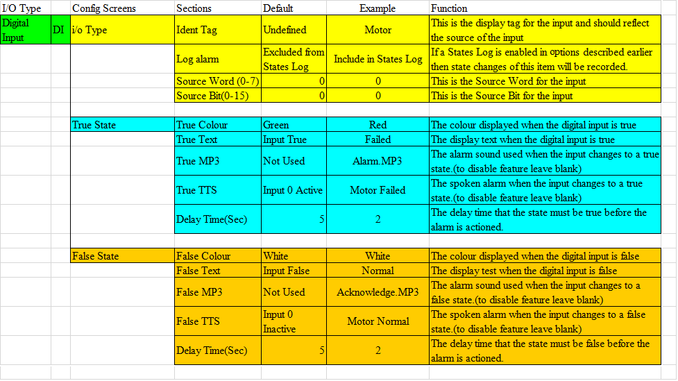
As mentioned above in the MODBUS configuration section we configured the digital inputs to have the following mapping.
In: 0 = 40001
In: 1 = 40002
In this example we have specified that the state that will be considered for this digital
input element will be located at Bit 0, Word 0 and this equates to Bit 0 of MODBUS location
40001.
We will consider the operation of this Digital Input later in the testing section below.
Before continuing click the "SAVE>CONFIG" button to save the interface so far to file.
AI - Analogue Input Element:
You may have noticed while changing between the three screens on the last section the
interface line at the top of the page is "Unlocked" while on the "i/o Type" page and "Locked"
while on the "True State" and "False State" pages.
I we check that we are on the "i/o Type" page then by touching the Interface Line indicator
(the button that now states it is unlocked) and a popup menu will allow you to change between
Interface lines, for now change the number from 0 to 1, the screen should then clear down
and the process type will once more state that the line is not used as before however this
time we are looking at the configuration for the second line.
Once again by pressing the "Line not used - press to change" we will be requested to choose
the function of this interface line, this time we should choose "Analogue Input" from the list,
although we could choose any of the options.
On doing so the screen should change to that below:
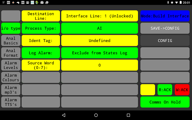
As before we need to supply specific information in order to build the Analogue input channel, the function of these are briefly outlined below:
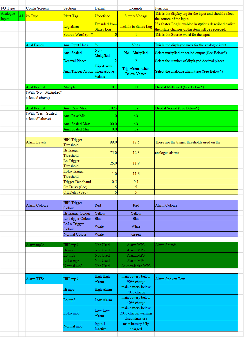
Scaling options-
As the source of the analogue input is a single signed binary word supplied by the MODBUS read,
in order to convert this into something that can easily represent real world values it must
first be manipulated in some way.
uSCADA(p) offers two ways in which this could be done, these are namely my multiplication or scaling.
Multiplication by a factor:
This signed binary word can represent a number range of +32767 to -32768, the simplest way to convert this to a value with decimal places is to simply multiply it by a factor. For example by multiplying this binary word with 0.1 then we now have an output range of +3276.7 to -3276.8. As long as we are careful not to over range this is a quick and simple way of representing real world numbers.
Scaling:
A more sophisticated way of producing a ranged output is to scale the signed binary word. This is useful when a a digital input device contains something like an ADC which will generate a known output depending on input.
For example the ADC may be connected to a potential divider so that the input range of 0-5 volts to the ADC represents the voltage of a supply battery of 0-15V. For a 10 bit ADC the output would then range from 0-1023 for an input of 0-15V. These factors could be entered into the program as that a direct representation of the input voltage could be displayed. To do this we would simply set the raw Max/Min values to 1023/0 and the scaled Max/Min values to 15.0/0.0.
Alternily if we wish to measure 4-20mA signals then if we pass the current though a 250ohm resistor and connect this to the channel, by scaling the channel to have raw Max/Min values of 1023/204 and the scaled Max/Min values to 20.0/4.0 a direct reading of the loop can be mesured.
Analogue Level Alarms-
As part of the configuration of the AI channel we have the option of setting up some analogue alarms, these are the HiHi, Hi ,Lo and LoLo references in the last half of the analogue input configuration. These can be setup to act in a number of ways and the simplest way to explain their operation is to refer to the drawing below:
In this diagram the default thresholds and deadband are represented.
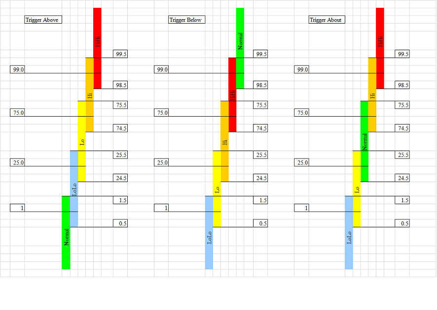
No Trigger Action
If this option is selected when no analogue alarms are required, if this option is used non of the other Alarm Trigger entries will have any effect.
Trigger Above
If this option is selected then with an input of 0-1.5 no alarms will sound, however as the input level increases then progressively the LoLo,Lo,Hi&HiHi alarms will sound.
Trigger Below
Alternately if this option is selected then with an input of 100-99.5 no alarms will sound, but as the input level decreases then progressively the HiHi,Hi,Lo&LoLo alarms will sound.
Trigger about
Finally if this option is selected then with an input of 24.5-75.5 no alarms will sound, however as the input level decreases then progressively the Lo&LoLo alarms will sound, conversely as the input increase above the mid range then the Hi&HiHi level alarms will be triggered.
The selection of which option is used depends heavily on the intended application, in the example above as we are monitoring the voltage of a battery we have selected the 'trigger below' option.
DO - Digital Output Element:
Once again in order to add another element to our project move back to the "i/o Type" page
and change the line number from 1 to 2, the screen should then clear down and the process
type will once more state that this line is not used.
Once again by pressing the "Line not used - press to change" cell we can select a function
type for this interface line.
If we select DO for digital output then the screen should change to:
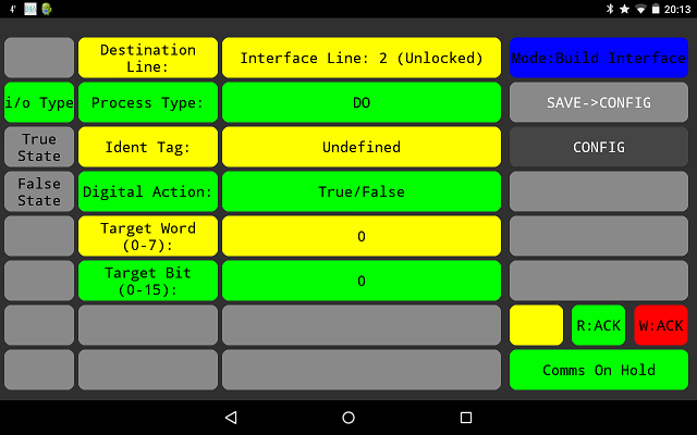
Once again to configure the interface line some basic information needs to be supplied as below:
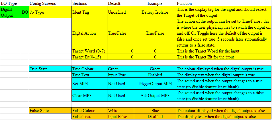
Most of this is self explanatory, the one thing that is worth noting is how the source and target Word/Bit addressing works.
If we recall previously the output MODBUS write was set to:
Out:0 = 40010
Out:1 = 40011
Therefore by setting the target word and bit to zero, we are actually targeting the output at bit
zero of 40010.
AO - Analogue Output Element:
The last of the IO types available is the Analogue output, to configure an interface line
to this function once again we must change the line number to one that is currently unused.
Currently we have programmed line 0,1 and 2 so if we change the line number to 3, the screen
should then clear down and the process type will once more state that this line is not used.
Once again by pressing the "Line not used - press to change" cell we can select a function
type for this interface line.
If we select AO for analogue output then the screen should change to:
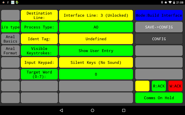
In order to configure the interface line to operate as desired we must supply
some data in order to guide its over all function, a breakdown of the
necessary data is as follows:
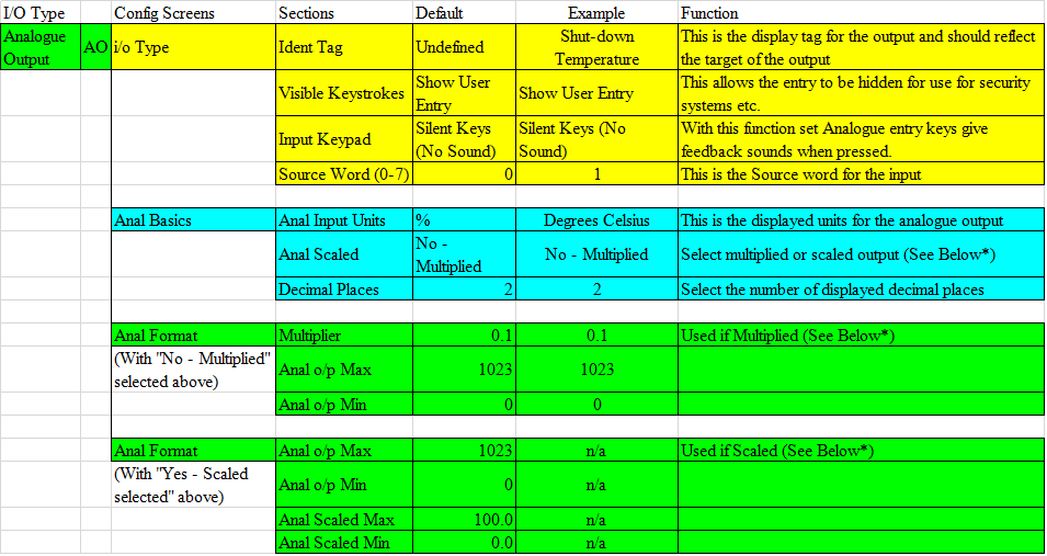
Once again the data can be scaled or multiplied before it is sent to the MODBUS location, the
user entry can be hidden and replaced with "*" and the key presses on the interface keyboard
can be set to give feedback.
Here we have opted for visible entry and multiplication with a factor of 0.1, for convenience
this factor is the same used for analogue inputs so strictly speaking should the the inverse of
the number shown. Here if the user enters 78.9 then 789 will be sent to 40011 as set up in the
MODBUS section previously.
Finally the last feature that is worth mentioning here is the function of the Anal o/p Max/Min when multiplying and Anal Raw Max/Min on scaling. These values act as the minimum and maximum
range of the data that can be sent to the target location and is intended to prevent data overruns
on the target register. If the Min/Max values have been exceed indication will be given on the
interface line, this will be outlined in the interface testing next.
|